Featured Industrial Components & Hydraulic Tooling Portfolio
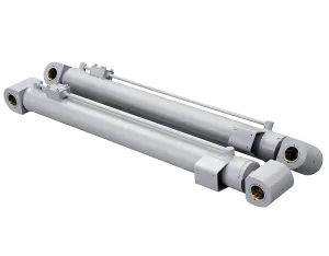
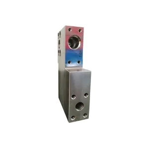
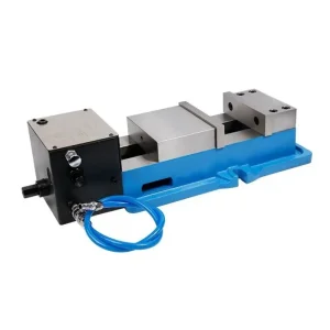
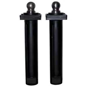
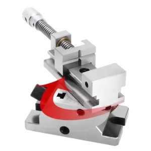
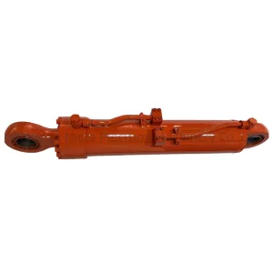
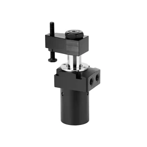
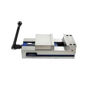
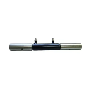
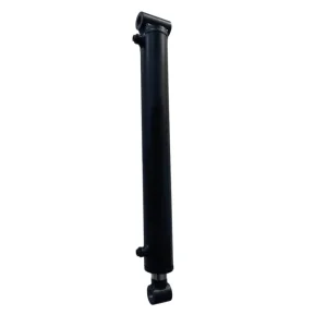
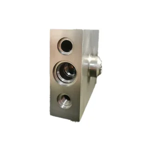
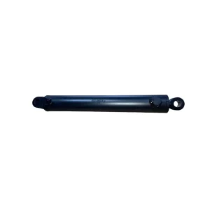
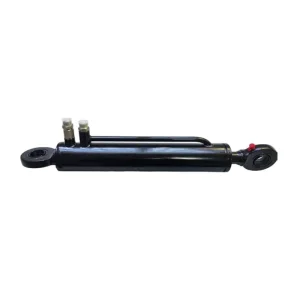
Explore our precision-machined heavy-duty hydraulic cylinders, high-pressure counterbalance valve manifolds, and universal CNC fixtures engineered under strict dimensional concentricity protocols.
Engineering DIN Tool Holder Pull Studs: The Mechanical Link of High-Velocity Machining
In contemporary multi-axis CNC milling centers, the retention knob (pull stud) is often the single most critical structural nexus between the tool holder cone and the machine drawbar mechanism. Operating under tensile clamping forces exceeding 20 kN, wholesale procurement mandates metallurgical precision without compromise.
DIN 69872 Form A & Form B Integrity
DIN 69872 defines rigorous geometric tapers, gripping angles, and internal through-coolant apertures. Form A features through-bore coolant pathways engineered to withstand up to 70 bar fluid delivery without hydraulic erosion, while Form B accommodates perimeter sealing rings designed for external high-pressure containment.
- Flawless 15-degree and 45-degree engagement tapers
- O-ring groove micro-finish (Ra ≤ 0.4 μm) prevents cavitation
- Strict adherence to ISO 7388/2-A interchangeability
Advanced Metallurgy: 20CrMnTi & SCM435
Pull stud failure represents catastrophic spindle wreck risk. Premium manufacturing uses high-purity alloy structural steels such as 20CrMnTi or SCM435, subjected to controlled carbonitriding or vacuum carburization to deliver a gradient hardness profile that mitigates notch sensitivity and brittle cleavage fracture.
- Hardened outer shell: 58-62 HRC resists gripper claw wear
- Elastic core: 32-38 HRC absorbs axial shock vibration
- Rolled threads eliminate micro-crack propagation
Dynamic Balance & High-Speed Runout
Modern machine spindles exceed 20,000 to 30,000 RPM in aerospace and precision mold fabrication. Eccentricity in the retention knob produces runout distortion, premature spindle bearing pitting, and tool-tip chattering that compromises workpiece Ra surface tolerances.
- G2.5 balance grading at 25,000 RPM per ISO 1940-1
- Concentricity controlled within 0.003 mm across pilot diameters
- Cryogenic deep freeze stabilizes residual austenite phases
Technical Specification Matrix: DIN vs. Global Pull Studs
Direct comparative review of taper compatibility, clamping head angles, coolant capabilities, and engineering safety factors across DIN 69872, ISO 7388, and JIS B6339 standards.
| Standard & Form | Taper Shank Fit | Gripping Angle (θ) | Coolant Channel | Thread Spec (Metric) | Target Core Toughness | Recommended Torque (Nm) |
|---|---|---|---|---|---|---|
| DIN 69872 Form A | SK40 / DIN 40 | 15° Taper Head | Central Thru-Bore (Ø 7.0 mm) | M16 x 2.0 | ≥ 850 N/mm² (32-38 HRC) | 85 ± 5 Nm |
| DIN 69872 Form B | SK50 / DIN 50 | 15° Taper Head | Solid / Outer Ring Sealed | M24 x 3.0 | ≥ 980 N/mm² (34-40 HRC) | 230 ± 10 Nm |
| ISO 7388/2-A | ISO 40 / BT40 Hybrid | 15° / Steep Chamfer | Through-Bore Available | M16 x 2.0 | ≥ 880 N/mm² (33-39 HRC) | 90 ± 5 Nm |
| ISO 7388/2-B | ISO 50 Standard | 45° Locking Flange | Central Or Radial Porting | M24 x 3.0 | ≥ 1000 N/mm² (35-40 HRC) | 240 ± 10 Nm |
| JIS B6339 (MAS 403) | BT30 / BT40 / BT50 | 45° / 60° / 90° | Solid or Thru-Coolant | M12 / M16 / M24 | ≥ 900 N/mm² (32-38 HRC) | 65 - 220 Nm |
Global Sourcing Dynamics: Mitigating Spindle Downtime and Total Cost of Ownership
Procurement teams navigating Tier 1 CNC tooling supplies face mounting pressures across lead times, metallurgical certifications, and batch consistency. Cheap, poorly heat-treated pull studs create catastrophic machine spindle damage that can exceed $30,000 per downtime event.
Direct Factory OEM/ODM Sourcing
By eliminating multiple tiers of wholesale distributors, global machining enterprises source directly from certified Chinese manufacturing plants. High-throughput CNC turning-milling centers provide volume scalability with tight unit cost economics and dedicated tooling customization.
- Custom thread relief angles for reduced stress nodes
- Direct laser marking with lot codes & QR tracking
- Container-level palletization with anti-corrosion VCI barrier
Fatigue Failure & Spindle TCO Analysis
Dynamic pull stud loading cycles occur hundreds of times per shift during automatic tool changing (ATC). Over-torquing or inferior base materials cause gradual shank elongation, distorting the tool holder taper within the spindle sleeve and degrading cutting tool life by up to 40%.
- Over-torque prevention via calibrated tightening flanges
- Radius transitions polished to prevent stress raisers
- Extended continuous duty: > 2,000,000 ATC cycles
EN 10204 3.1 Certified Compliance
Aerospace, medical, and defense machining demands complete metallurgical provenance. Quality-focused factories provide EN 10204 3.1 inspection certificates documenting chemical spectral analysis, yield strength, tensile elongation, and dimensional CMM inspection reports.
- Spectrometric heat batch chemistry verification
- Case depth microhardness profiling (0.8 - 1.2 mm depth)
- RoHS & REACH compliant black oxide or nickel finishes
Technology Roadmap: Intelligent Clamping & Next-Gen Tool Holding
As automated smart manufacturing centers transition toward Industry 4.0 lights-out production, pull stud engineering is evolving from passive mechanical retainers into sensor-monitored, data-connected machine elements.
Embedded RFID Chips
Integration of miniature UHF RFID tags directly within the non-stressed pull stud boss, logging cumulative drawbar cycles, tooling lifespan, and tool setup parameters for zero-error ATC operations.
Nanocomposite PVD Coatings
Application of low-friction diamond-like carbon (DLC) and titanium aluminum nitride (TiAlN) coatings to the retention knob contact heads, drastically lowering fretting corrosion against gripper fingers.
High-Pressure Coolant Geometry
Hydrodynamically simulated internal radii supporting continuous 100+ bar high-pressure through-spindle coolant (TSC), eliminating turbulence drag and chip re-cutting in deep-hole titanium drilling.
Integrated Strain Gauges
Experimental wireless piezoelectric micro-transducers transmitting real-time clamping force telemetry to CNC controllers, instantly detecting drawbar spring fatigue prior to spindle crashes.
Frequently Asked Technical & Sourcing Questions
In-depth technical answers for machining shop managers, toolroom engineers, and global procurement officers sourcing DIN tool holder pull studs.
What is the structural difference between DIN 69872 Form A and Form B pull studs?
DIN 69872 Form A features a through-hole (central bore) specifically engineered for internal through-spindle coolant (TSC) delivery, terminating in a precision chamber that seals against the machine drawbar nozzle. In contrast, DIN 69872 Form B features a solid central axis or blind hole, utilizing an external O-ring recess groove positioned on the collar flange to retain coolant pressurized between the tool holder cone and the spindle arbor.
Why is case hardening superior to through-hardening for high-speed retention knobs?
Through-hardened pull studs become brittle throughout their entire cross-section. When subjected to the high cyclic tension of automatic tool changers combined with severe interrupted cuts, through-hardened steel is susceptible to catastrophic brittle fracture. Case-hardened 20CrMnTi provides an outer wear-resistant shell (58-62 HRC) to withstand gripper claw fretting, backed by a ductile, shock-absorbing low-carbon alloy core (32-38 HRC) that prevents notch fracture.
How does improper tightening torque affect tool holder taper expansion?
Over-torquing a retention knob introduces extreme hoop stress into the narrow small-end taper of the tool holder. This causes measurable elastic expansion (bell-mouthing) of the 7:24 taper, reducing full-surface taper contact with the machine spindle from 85% down to less than 40%. The resulting loss of contact rigidity induces severe vibration, accelerated runout, and premature spindle bearing failure. Always utilize a calibrated torque wrench to the exact manufacturer specification (e.g., 85 Nm for SK40/M16).
What quality control methods ensure zero-defect wholesale shipments?
Tier 1 wholesale production incorporates 100% Magnetic Particle Inspection (MPI) to identify subsurface fatigue fractures and microscopic quench fissures. Thread dimensions are verified via automated optical video measuring machines and 6H GO/NOGO thread gauges. Concentricity between the pilot shank, clamping head, and thread axis is held under 0.003 mm on precision concentricity test benches.
Can DIN 69872 pull studs be utilized in ISO 7388 or BT standard holders?
DIN 69872 pull studs utilize metric threads (M16 for 40-taper, M24 for 50-taper) and are directly interchangeable with ISO 7388/2-A tool holders when the drawbar gripper system is configured for 15-degree engagement. However, they cannot be mixed with JIS B6339 (MAS 403 BT) spindles unless the gripper system is specifically re-spaced, as BT retention knobs feature distinctly different gauge lengths (L1) and head angles (typically 45, 60, or 90 degrees).
What is the standard production lead time and minimum order quantity (MOQ) for custom configurations?
For standard catalog DIN 69872 Form A and B studs, inventory is typically maintained for immediate dispatch in batch quantities of 500 to 10,000 units. For custom OEM lengths, through-coolant modifications, or specialized DLC anti-wear coatings, standard pilot tooling and production cycles require approximately 15 to 25 working days with minimum order thresholds starting at 200 units.
Expanded Hydraulic Cylinders & CNC Workholding Series
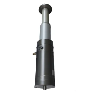
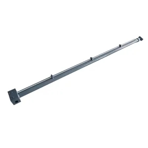
Comprehensive mechanical components built to rigorous international engineering tolerances, featuring our telescopic boom cylinders, heavy-duty pressure relief manifolds, and precision universal vises.