Precision Hydraulic & Mechanical Assemblies
Engineered for seamless integration into high-load hydraulic systems, structural workholding, and pressure control circuits.
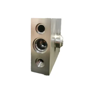
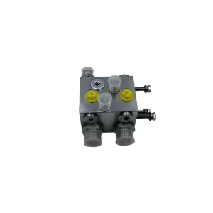
Macro Hydraulic Solutions: The Central Role of Overflow Valve Blocks
In modern high-pressure fluid power, the overflow valve block (often designated as the primary main relief manifold) is the cornerstone of mechanical safety, operational longevity, and circuit thermal regulation.
System Overpressure Containment
Sudden valve spools shifting, extreme mechanical stalls, or external shock loads generate destructive pressure spikes exceeding 500 bar. Certified overflow valve blocks provide instantaneous cracking response (<10 ms) to shunt excess volumetric flow back to tank, eliminating structural line ruptures.
Parasitic Loss & Heat Dissipation
Uncontrolled continuous overflow creates fluid shearing, causing catastrophic viscosity breakdown and seal destruction. Precision-engineered internal galleries reduce flow resistance by up to 28%, preserving hydraulic fluid integrity and minimizing active cooling demands in demanding continuous-duty cycles.
Manifold Cavity Standardization
Consolidated overflow manifolds accommodate standardized screw-in cartridge valves (SUN, HydraForce, Bosch Rexroth cavities such as T-10A, T-2A, or VC standard). This enables streamlined multi-stage piloting, electrical proportional relief overrides, and fail-safe mechanical backups on a singular footprint.
Global Commercial Dynamics: Evaluating the Best Overflow Valve Block Factories
The global fluid power supply chain has transitioned from decentralized piping to integrated manifold blocks. Sourcing managers navigate distinct regional factory tiers across Europe, North America, and premier East Asian manufacturing hubs.
| Evaluation Parameter | Tier-1 Western OEMs | Micro Precision Machinery (MPM China) | Generic Commodity Workshops |
|---|---|---|---|
| Base Metallurgy | Ductile Iron (GGG40/60) / Aircraft Aluminum 7075 | QT500-7 Continuous Cast Iron / AL6061-T6 / Steel 45# | Scrap-mixed cast iron / Uncertified porous billets |
| Bore Honing & Deburring | Thermal Deburring (TEM) & High-Pressure Flush | Cross-Hole Extrude Honing & Ultrasonic Degreasing | Manual hand deburring (High flash & particle risk) |
| Port Tolerancing | ISO 6149 / SAE J1926 (Class 2B) | Standardized Metric, SAE, & BSPP with 6H threads | Rough tapped threads with inconsistent depths |
| Economic Lead Times | 16 to 26 Weeks (Rigid backlogs) | 3 to 5 Weeks (Agile CNC production cells) | 4 to 8 Weeks (Frequent quality delays) |
| Traceability & Testing | Full 3.1 Mill Certs & Pressure Charts | CMM Inspection, Material Certs & Hydrostatic Test Data | Visual inspection only (No pressure holding cert) |
Localized Support & Stringent International Compliance
A premier overflow valve block factory must eliminate interface risk across borders. Our manufacturing infrastructure aligns with stringent worldwide engineering standards.
ISO 4406 Cleanliness Rigor
Every overflow block undergoes high-pressure solvent flushing and ultrasonic sonic baths to ensure internal passages meet ISO 4406 Class 16/14/11 particle thresholds, stopping early spool binding.
Pressure Equipment Directive (PED)
All cast and forged bodies are certified to EU PED 2014/68/EU standards. Blocks carry bursting safety safety margins up to 300% above stated operational relief limits without mechanical failure.
Interchangeable Port Standard
Machined directly to metric (DIN 3852), SAE (J1926-1), or British Standard (BSPP ISO 1179). This guarantees drop-in field replacement without field adaptations or re-piping expenses.
Surface Passivation & Plating
Surfaces receive zinc-nickel plating (surpassing 720 hours salt spray ASTM B117), black anodizing for marine grade aluminum, or chemical phosphating for harsh industrial exposure.
High-Stress Application Scenarios
Discover how precision overflow and relief manifolds function within demanding real-world industrial environments.
Heavy Earthmoving & Mobile Excavators
Boom and arm hydraulic circuits experience continuous dynamic shocks when buckets contact bedrock. Custom overflow valve blocks relieve auxiliary peak pressure lines instantly, preventing main pump case backpressure spikes while holding cylinder position via tight-tolerance internal pilot circuits.
High-Tonnage Industrial Stamping Presses
In metalforming and powder presses, multi-stage relief blocks manage rapid decompression sequences. Controlled pilot-operated overflow ensures smooth release of compressed fluid before press opening, eliminating catastrophic hydraulic shock ("water hammer") across high-pressure pipe runs.
Underground Mining Loaders (LHD)
In confined tunnel mucking, equipment operates under intense thermal stress and dust contamination. MPM ductile iron overflow manifolds integrate compact relief and reverse flow check cavities to protect underground steering and hoisting lines under continuous 24/7 operating cycles.
Engineering Roadmap: The Next Era of Overflow Blocks
Hydraulic manifolds are advancing from static iron blocks into responsive, sensor-integrated control systems.
CFD-Optimized Internal Flow Routing
Utilizing 3D computational fluid dynamics (CFD) to design curved transition radii inside manifolds. Eliminating traditional orthogonal drilled dead-ends reduces localized fluid turbulence, drops cavitation wear by 40%, and lowers energy draw on the primary motor drive.
Additively Manufactured Titanium Manifolds
Selective Laser Melting (SLM) enables complex internal lattices and curved internal galleries impossible with traditional CNC tooling. This yields up to a 60% manifold weight reduction—critical for aerospace, military, and mobile boom applications requiring minimal swing inertia.
Embedded IIoT Sensor Integration
Next-generation valve blocks feature embedded micro-cavities for digital IO-Link pressure sensors, temperature probes, and spool-displacement monitors. Continuous health analytics detect poppet seat erosion or micro-leakage before mechanical system disruption occurs.
Need Custom Cavity Milling or Engineering Blueprint Review?
Our engineering team in Qingdao reviews customer STEP files, schematic circuit designs, and OEM cavity specifications within 24 hours.
Frequently Asked Technical Questions (FAQ)
Essential guidance on specifying, machining, and procuring high-pressure overflow and relief manifolds.
What is the difference between an overflow valve block and a safety relief valve block?
When should I choose continuous-cast ductile iron over aircraft aluminum?
How does MPM ensure cross-hole intersections are free of damaging burrs?
Can you manufacture custom valve blocks directly from hydraulic schematics?
What surface treatment is best for coastal or marine hydraulic power units?
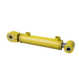
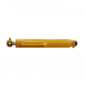
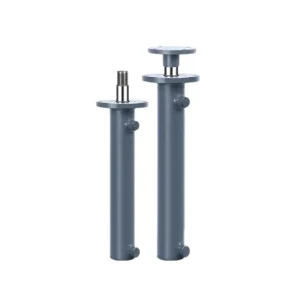
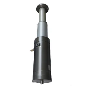
Precision Hydraulic Cylinders & Industrial Tooling
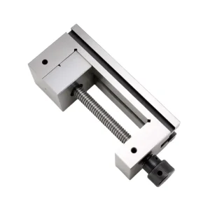
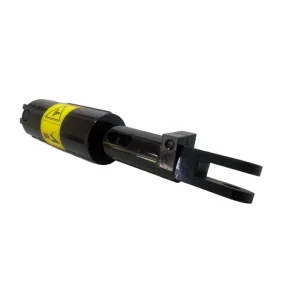
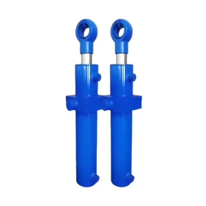
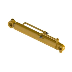
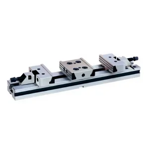
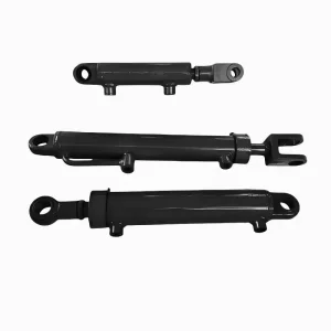
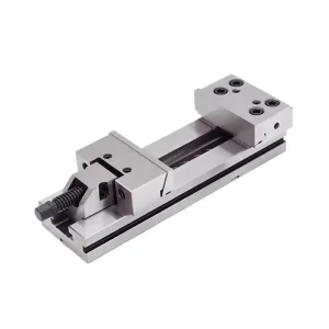
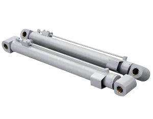
Complementary hydraulic actuators, telescoping cylinders, and precision workholding accessories machined in our Qingdao facility.