
High-Precision Hydraulic Actuators & Components
Verified OEM configurations manufactured to microscopic tolerances in our Qingdao facility, delivering consistent pressure boundaries and load-locking stability.
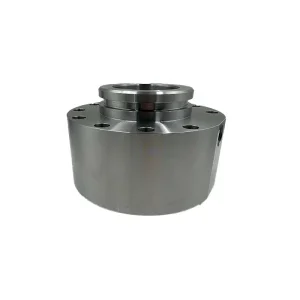
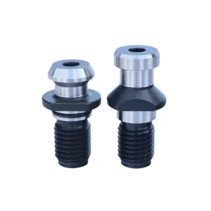
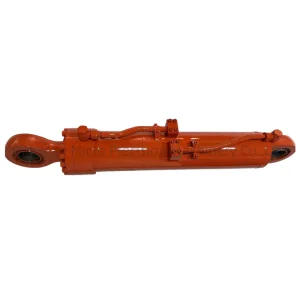
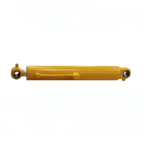
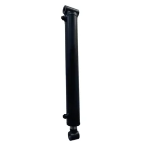
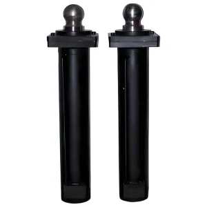
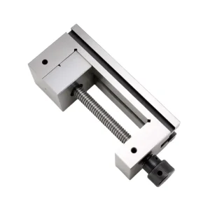
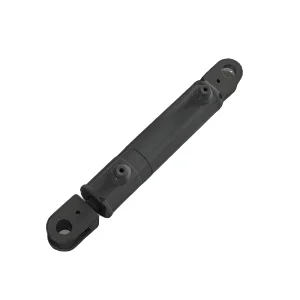
The Architecture of Counterbalance & Overcenter Valves
Comprehensive design principles governing load holding, motion modulation, line rupture protection, and thermal expansion mitigation across high-pressure fluid circuits.
Static Load Holding & Zero Drift
Counterbalance valves (also termed overcenter valves) serve as hydraulic locking mechanisms designed to sustain suspended loads indefinitely without gravitational sagging. Unlike spool-type directional control valves that suffer from unavoidable radial clearance leakage, our cartridge poppets utilize hardened steel-on-steel conical seats.
This micro-lapped interface maintains internal fluid leakage below 3 drops per minute at 80% of nominal cracking pressure, preventing catastrophic cylinder creep in crane boom lifters, aerial platforms, and underground mining equipment.
Dynamic Overrunning Control
When external gravitational or inertial forces pull an actuator faster than the hydraulic pump supplies fluid, cavitation and uncontrollable runaway motion occur. The counterbalance valve throttles the return oil flow from the cylinder's annulus or bore cavity, dynamically matching pump inlet flow.
By modulating the backpressure against the piston, the valve guarantees smooth, chatter-free descent across boom retraction, winch lowering, and excavator bucket tipping, irrespective of shifting load vectors.
Hose-Burst Catastrophe Protection
Plumbing failures in high-pressure hydraulic circuits represent extreme safety risks. When integrated directly into cylinder end-caps or manifold-mounted via rigid flange SAE J518 code 61/62 ports, our valves immediately isolate the fluid volume if an upstream hydraulic hose ruptures.
Operating with a mechanical response threshold under 15 milliseconds, the check poppet slams shut, mechanically trapping hydraulic oil within the cylinder barrel and preventing free-fall accidents on construction sites.
Pilot Ratio Selection & Equilibrium Dynamics
The functional heart of an overcenter counterbalance valve is the pilot ratio ($R_p$), representing the surface area differential between the internal pilot piston and the relief seat. The pressure required to initiate flow ($P_{pilot}$) is governed by load-induced pressure ($P_{load}$), relief valve cracking pressure ($P_{crack}$), and the pilot ratio:
| Pilot Ratio ($R_p$) | Dynamic Characteristics | Recommended Operating Envelope | Stability vs Efficiency |
|---|---|---|---|
| 3:1 to 4.5:1 (Standard / Low Ratio) |
Exceptional circuit stability; highly immune to hydraulic resonance and pressure spikes. Requires greater pilot pressure to modulate lowering motion. | Mobile cranes, rough-terrain boom lifts, long-span aerial work platforms, winches handling varying structural elasticity. | Highest stability rating; nominal parasitic energy consumption during powered lowering cycles. |
| 8:1 to 10:1 (High Ratio) |
Ultra-responsive opening dynamics; minimizes the horsepower lost to backpressure. Higher sensitivity to pump pulsations and rapid load shedding. | Excavator digging circuits, underground mining loaders (LHD), continuous cycling industrial presses where energy conservation is paramount. | Maximum hydraulic efficiency; requires precise pilot line dampening orifices to suppress potential hydraulic chatter. |
| Custom Dual-Stage / Vented | Atmospherically vented or pilot-vented cartridges insensitive to downstream backpressure variations in closed-center load sensing systems. | Electro-hydraulic proportional load-sensing (LS) circuits, variable displacement motor drives, high-duty automated machinery. | Complete isolation from variable tank line return backpressure; eliminates erratic valve resetting. |
China Factory Ecosystem: Micron-Level Engineering Mastery
Combining vertically integrated casting foundries, 5-axis DMG MORI machining clusters, and ISO 17025 certified testing laboratories to overcome global sourcing bottlenecks.
Cavity & Spool Precision
Our Qingdao machine shop operates high-precision multi-axis machining centers dedicated to industry-standard cartridge cavities (including SUN T-11A, T-2A, T-17A, and Rexroth standard cavity interfaces).
Internal sleeve bores and spool diameters are matched with diametrical clearances of 0.003 mm to 0.005 mm via diamond grinding and CNC cross-hatching, virtually eliminating fluid bypass.
Continuous Metallurgical Control
Valve manifolds are manufactured utilizing continuous-cast ductile iron (QT500-7 / GGG50) or high-tensile 6061-T6511 aluminum alloy. Ductile iron bodies withstand dynamic pressure cycles up to 420 bar (6,000 PSI) without micro-fissuring.
Internal poppets and sleeves are forged from 20CrMo or 40Cr alloy steel, vacuum-carburized to 58-62 HRC for indefinite resistance to fluid erosion.
Supply Chain Clustering
Situated in Qingdao, Shandong province—the global epicenter for construction machinery manufacturing—Qingdao Micro Precision Machinery benefits from localized component clusters. Raw forgings, specialized fluorocarbon seals (Viton/FKM), and heat-treatment facilities are located within a 30-mile radius.
This geographic integration cuts prototyping lead times down to 10 days and mass production batches to under 4 weeks.
100% Digital Flow Testing
Zero statistical sampling: every single counterbalance valve assembly undergoes mandatory multi-point testing on automated hydraulic test benches before boxing.
Testing matrices verify seat leakage, cracking pressure hysteresis, pilot pressure threshold, and thermal relief pop-off values under ISO 4406 cleanliness conditions (Class 16/14/11), archived via digital serial tracing.
Global Enterprise Sourcing & Quality Standards
Addressing the stringent engineering mandates, compliance frameworks, and logistics requirements of Tier-1 OEMs across North America, Europe, and Asia-Pacific.
Regulatory Directives & Global Harmonization
Global original equipment manufacturers require strict compliance guarantees when integrating critical hydraulic safety mechanisms:
- Machinery Directive 2006/42/EC & ISO 4413: All hydraulic assemblies comply with rigorous structural factor margins (minimum 4:1 burst pressure burst factor) and fail-safe locking standards.
- Material Certification EN 10204 Type 3.1: Complete chemical composition and tensile elongation documentation tracing every batch of ductile iron and alloy steel directly back to the blast furnace.
- Environmental Stewardship: Surface zinc-nickel plating guarantees over 720 hours of salt spray exposure (ASTM B117) with absolute RoHS and REACH hexavalent-chromium-free compliance.
- Thread Standard Flexibility: Full tooling availability for metric ISO 6149, British Standard BSPP (ISO 1179), and North American SAE J1926 (UNF) O-ring ports.
Supply Assurance & Engineering Traceability
Procurement teams require agile risk management and uninterrupted continuity across multinational supply chains:
- PPAP Level 3 Integration: Production Part Approval Process including Gage R&R, FMEA risk assessments, process flow diagrams, and dimensional verification reports for custom ODM manifolds.
- Direct Cylinder-to-Valve Pairing: As an integrated manufacturer of both hydraulic cylinders and valve manifolds, Micro Precision Machinery eliminates interface compatibility issues between cylinder barrels and counter balance valve blocks.
- Air, Sea, and Rail Hubs: Rapid multi-modal transit through the Port of Qingdao, ensuring direct consolidated shipping to European and North American manufacturing hubs with DDP terms.
- Barcode & RFID Serialization: Unit-level laser etched QR identifiers for immediate traceability of assembly dates, test records, and material heats.
Mission-Critical Applications in Hostile Environments
Engineered to handle extreme cyclic shocks, abrasive airborne particulates, corrosive saline spray, and heavy continuous vibration across demanding industries.
Underground Mining Loaders (LHD)
Deep underground mining operations place extreme demands on lift and tilt actuators. Confined tunneling limits cooling airflow, subjecting hydraulic fluids to elevated thermal states up to 90°C.
Our counterbalance manifolds feature Viton high-temperature seals and custom dampening check valves that absorb heavy dynamic bucket shocks during blasting muck-out operations without cracking prematurely.
Telescopic Mobile Cranes & Luffing
Mobile crane boom extensions demand flawless proportional feathering. Structural flexure in long crane booms causes rapid elastic load changes that can trigger violent hunting or oscillatory valve bounce.
Utilizing custom 4.5:1 pilot cartridges paired with integrated pilot restriction check orifices, our valves dampen oscillatory feed back, ensuring millimeters of precision during high-altitude structural steel erection.
Aerial Work Platforms (AWP)
Human safety mandates absolute zero tolerance for cylinder drift. Articulated boom lifts and scissor platforms are exposed to changing outdoor weather, requiring smooth, jerk-free starting and stopping to prevent platform sway.
Our T3A integrated blocks incorporate a thermal expansion relief feature that bleeds excessive pressure caused by solar heating of trapped cylinder oil, keeping systems fully within safe margins.
Next-Generation Motion Control & Smart Valve Trends
The convergence of electro-hydraulic integration, digital load balancing, zero-emission electric machinery, and additive manufacturing across fluid power ecosystems.
Digital Proportional Electro-Hydraulics
The rapid electrification of compact excavators and wheel loaders requires intelligent energy management. Traditional mechanical counterbalance valves dissipate kinetic lowering energy as heat.
Micro Precision Machinery is actively advancing electro-proportionally controlled overcenter cartridges capable of dynamic CAN-bus communication with machine control units (MCUs), enabling continuous pilot pressure modulation and energy regeneration.
Additive Flow-Optimized Channels
Traditional manifold blocks require cross-drilled internal conduits plugged with ball seals, creating sharp 90-degree junctions, fluid turbulence, and cavitation risk.
Utilizing computational fluid dynamics (CFD) and direct metal laser sintering (DMLS) 3D printing for specialized prototypes, curved internal fluid galleries reduce internal pressure drops by up to 28%, significantly boosting total hydraulic battery efficiency on electric machinery.
Direct Cartridge Cylinder Integration
External hydraulic tubing between the cylinder port and the valve body introduces compliance, elasticity, and potential rupture points. Modern mobile architecture demands complete consolidation.
Our Qingdao engineering center specializes in custom integrated cylinder heads and barrels where the counterbalance valve cavity is bored directly into the cylinder's solid forged base or gland, reducing installation envelopes and weight.
5-Stage OEM/ODM Quality Validation Workflow
Every custom valve cavity, machined manifold, and hydraulic assembly follows a documented, repeatable manufacturing framework from raw stock through certified export packaging.
Hydraulic Simulation & Drawing Freeze
Our fluid power engineers review your circuit schematics, load envelopes, and transient backpressures. 3D solid modeling ensures optimal manifold wall thicknesses, eliminating rupture risks under 3x pressure surges.
Sub-Micron CNC Manifold Machining
Blocks are cut on high-speed machining centers equipped with precision tooling. Form cavities (SUN/Rexroth compatible) are bored with dedicated reamers to guarantee concentricity and Ra 0.4 surface finishes.
Thermal Deburring & Ultrasonic Wash
Machined manifolds undergo thermal energy method (TEM) deburring to vaporize burrs from intersecting oil passages, followed by multi-stage ultrasonic degreasing to achieve ISO 4406 Class 16/14/11 cleanliness.
100% Multi-Parameter Bench Test
Each cartridge and manifold is tested for cracking pressure, pilot opening curve, flow hysteresis, and high-pressure seat leakage. Digital pressure transducers capture and log performance curves for every serial number.
Preservation, Nitrogen Sealing & Export Dispatch
Ports are capped with high-density threaded plugs. Assemblies are treated with anti-corrosion barrier oil, vacuum-wrapped, and packed in reinforced export-grade plywood crates for transit via Qingdao port.
Engineering & Sourcing Technical Inquiries
Answers to critical questions asked by machine designers, procurement directors, and OEM engineers before sourcing hydraulic counterbalance valves from China.
How do I determine the correct pilot ratio for my mobile machinery circuit?
Selecting the ideal pilot ratio is a calculated balance between circuit stability and parasitic energy loss. A lower pilot ratio (such as 3:1 or 4.5:1) provides maximum operational stability and resistance to hydraulic chatter, making it ideal for flexible structural loads such as aerial work platforms, truck crane booms, and winches. A higher pilot ratio (8:1 or 10:1) requires significantly less pilot pressure to release the load, optimizing fuel efficiency and cycle speed in rigid structures like excavators and mining scoops. Our engineering team calculates load dynamics, cylinder stroke elasticity, and backpressure fluctuations to recommend the exact ratio for your duty cycle.
Can Qingdao Micro Precision Machinery duplicate existing SUN or Rexroth cavities?
Yes. We maintain complete tooling sets and specialized CNC form cutters for all international cartridge valve cavities, including SUN standard cavities (T-11A, T-2A, T-17A, T-19A) and Rexroth/Bucher industry-standard metric cavities. You can procure our fully assembled valve blocks, customize custom manifolds to house your existing cartridge inventory, or source our complete line of pre-tested replacement cartridge valves guaranteed to fit existing cavities with zero modification.
What is the standard internal seat leakage allowance for your counterbalance cartridges?
All our counterbalance check and relief poppets utilize precision heat-treated (58–62 HRC) alloy steel that is micro-lapped against hardened seats. Internal seat leakage is guaranteed below 3 drops per minute (less than 0.15 cc/min) at 80% of nominal relief cracking pressure using standard ISO VG 46 mineral hydraulic oil at 40°C. For critical aerospace or specialized underground holding applications, we can supply specialized soft-seated cartridges achieving true zero-leak performance.
How do your manufacturing facilities prevent manifold cracking under high cyclical pressure?
Manifold integrity is guaranteed through careful raw material selection and advanced machining processes. For operating pressures up to 420 bar (6,000 PSI), we utilize continuous-cast ductile iron (QT500-7 / GGG50) rather than sand-cast blocks, eliminating internal voids, pinholes, and micro-porosity. Manifold port wall thicknesses are validated using finite element analysis (FEA), with burst test testing performed at 4x working pressure. For mobile aluminum blocks, we exclusively source certified aircraft-grade 6061-T6511 aluminum billet with hard-anodized surface finishes.
What information is required to receive a formal OEM/ODM engineering quote?
To deliver an actionable engineering proposal and cost analysis within 24 hours, our technical team requires: hydraulic schematic diagram, maximum system operating pressure, peak load-induced pressure, maximum pump flow rate (L/min or GPM), desired pilot ratio, fluid type and working temperature envelope, cylinder port sizes and mounting constraints, and projected annual production volumes. If you are reverse-engineering an existing manifold, physical samples or STEP 3D CAD files can be reviewed directly.
How are international shipments protected against salt air corrosion during ocean transit?
All exposed external steel surfaces undergo multi-layer zinc-nickel electroplating or manganese phosphating providing over 720 hours of salt spray resistance (ASTM B117). Internal chambers are flushed with vapor-corrosion-inhibiting (VCI) testing oil, all ports are sealed with heavy-duty threaded plugs, and entire manifolds are hermetically sealed inside heat-shrink VCI barrier film with desiccant packs before crating into ISPM-15 compliant fumigated plywood cases.
Precision Motion Actuators & Specialized Tooling
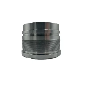
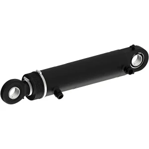
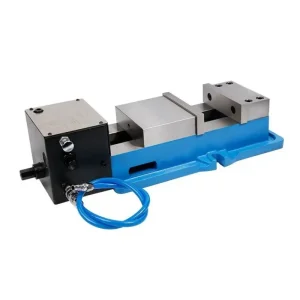
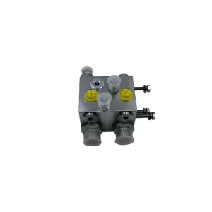
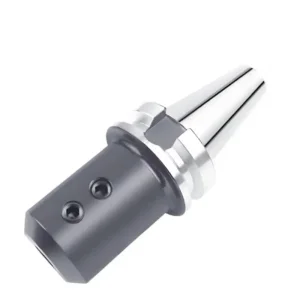
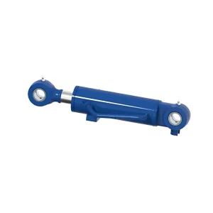
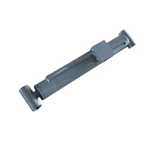
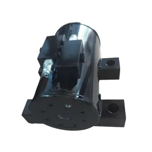
Explore our complete manufacturing portfolio—from CNC tool retention systems and pneumatic vices to heavy duty suspension and steering cylinders.
Connect Directly With Our Fluid Power Engineering Team
Send your hydraulic schematics, CAD envelope files, or replacement specifications. Our technical department reviews your application and responds within 24 hours with certified manufacturing calculations, DFM optimization, and fixed quotation.
Submit Engineering Drawing for Review