
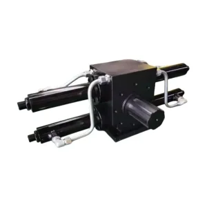
OEM Production Line · Series A
Precision Actuators, Manifold Blocks & Turn-Key Assemblies
Direct from Qingdao Micro Precision Machinery: explore critical hydraulic sub-systems fabricated with exact metallurgical tolerances, multi-axis CNC repeatability, and verified dynamic seal profiles.
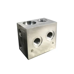
Cheap T13A Hydraulic Flow Control Valve Block MPM-HFCVB13A Supplier, Manufacturers
Product Details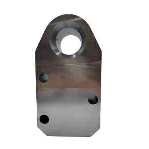
Custom Integrated Cylinder Barrel MPM-HCIB11 Supplier, Manufacturers
Product Details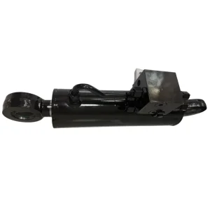
China Reversible Plough Turnover Hydraulic Cylinder Suppliers, Manufacturers
Product Details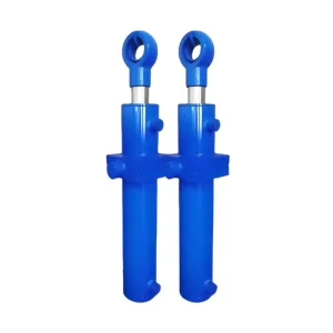
Custom Telescopic Cylinder Supplier, Manufacturer
Product Details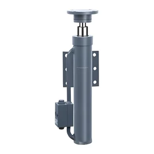
Wholesale Outrigger Expansion Cylinder Suppliers, Factory
Product Details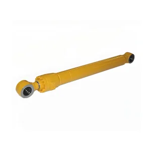
Cheap Boom Cylinder MPM-HCB212 for Excavator and Loader Manufacturer, Factories
Product Details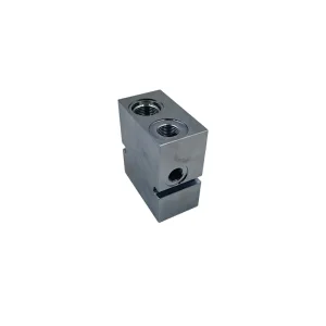
China Lift Cylinder Solenoid Valve MPM-LCSV12 Manufacturers, Factory
Product Details
Industrial Fluid Power Engineering Whitepaper
The Mechanics of Welded Relief Valve Mounting Bases
An authoritative metallurgical analysis on transient surge absorption, cavity seat geometry, thermal heat-affected zone (HAZ) mitigation, and leak-free hydraulic cylinder barrel integration.
Cavity Micro-Precision & Sealing
Screw-in cartridge valves (e.g., Sun Hydraulics T-10A, T-2A, HydraForce VC08-2) demand absolute structural roundness within the welded mounting base. Even sub-micron ovality under heat warps the internal sleeve, resulting in internal weeping or delayed spool actuation.
- Cavity concentricity held within ≤ 0.008 mm
- Surface roughness down to Ra 0.4 µm on valve seats
- Zero galling on UN/UNF and metric threads
HAZ & Cylinder Bore Distortion
Directly welding a heavy forged relief valve mounting base onto a cold-drawn ST52-3 or 27SiMn barrel induces severe thermal gradients. Without optimized preheating and weld-neck beveling, the cylinder inner diameter contracts or becomes elliptical, shredding piston seals.
- Custom radiused saddles matched to barrel O.D.
- Automated MAG / Submerged-Arc penetration
- Internal barrel bore deflection below 0.015 mm
Impulse & Surge Dampening
When excavators or heavy cranes encounter sudden mechanical resistance, line-rupture safety or overload relief valves must crack within milliseconds. Welded bases form a continuous rigid structure that eliminates vulnerable high-pressure fitting joints.
- Hydrostatic test pressure proofed to 1.5× working load
- Eliminates hydraulic leak paths & hose bursts
- Resists fatigue cracking over 2,000,000 pulse cycles
2006
Founded in Qingdao, China
420 Bar
Rated Peak Pressure Endurance
20,000
Monthly Unit Manufacturing Capacity
50+
Global Heavy OEM Collaborations
Global Sourcing Matrix & Metallurgy
Comprehensive Raw Material & Manufacturing Specification
Selecting the correct alloy for welded relief valve blocks governs weld integrity, thread retention, and anti-cavitation erosion performance under high hydraulic velocities.
| Material Standard | Yield Strength (Re, MPa) | Tensile Strength (Rm, MPa) | Weldability Index (CEV) | Recommended Industrial Application | Quality Verification Test |
|---|---|---|---|---|---|
| ASTM A105 / C22.8 (Forged Carbon Steel) | ≥ 250 | 485 – 650 | 0.38 – 0.44 (Superior) | Standard Excavator Boom/Arm Relief Sub-bases | EN 10204 3.1, UT Flaw Detection Grade A |
| 16Mn / Q355B (ST52-3) Low Alloy High Tensile | ≥ 355 | 490 – 630 | 0.36 – 0.40 (Excellent) | Heavy Mining LHD Actuators, Mobile Cranes | Charpy V-Notch Impact Test at -40°C (≥ 27 J) |
| AISI 1045 / 45# Steel (Quenched & Tempered) | ≥ 355 | ≥ 600 | 0.50 – 0.58 (Preheat Req.) | High-Pressure Clamping Manifolds, CNC Workholding | Magnetic Particle Inspection (MPI), Surface Hardness 28-32 HRC |
| AISI 316L / 1.4404 (Austenitic Stainless) | ≥ 220 | 520 – 680 | Negligible HAZ hardening | Offshore Marine Winches, Chemical Flow Regulators | ASTM A262 Practice E (Intergranular Corrosion) |
| 6061-T6511 (Hydraulic Aluminum Alloy) | ≥ 276 | ≥ 310 | N/A (Bolted/Sub-plate only) | Lightweight Aerial Work Platforms (AWP) Manifolds | Anodizing Thickness Verification ISO 2360 (≥ 25 µm) |
Need Custom Bevel Radiuses or Direct-Mount Saddle Geometries?
Our Qingdao engineering division reviews client 2D CAD files (DWG/DXF) and 3D native models (STEP/IGES) within 24 hours. We match cylinder barrel curvatures precisely to eliminate edge gap stress concentrations during root welding.
Field Deployment Architecture
Mission-Critical Application Environments
Welded relief valve blocks act as the final failsafe barrier guarding expensive hydrostatic machinery from destructive pressure spikes.
Underground Mining Loaders (LHD)
In narrow underground stope operations, mining buckets endure violent rock wedging shocks. Welded relief bases mounted directly on the lift/tilt barrels vent peak pressures instantly to tank line, preserving hydraulic seals from catastrophic rupture.
- Eliminates intermediate pipe fittings in toxic dust areas
- Resists extreme high-frequency vibration and impact
- Designed for rapid in-situ cartridge valve replacement
Heavy Construction & Earthmoving
Excavator booms, bulldoze blades, and multi-stage wheel loaders experience fluctuating side-load forces. Welded mounting sub-plates provide direct integration for dual-cushion relief valves and counterbalance flow check manifolds.
- Compact envelope fits within tight boom boom-box cavities
- Direct integration with cylinder barrel ports avoids pressure drops
- Fully certified for sub-zero operation (-40°C Arctic grading)
Agricultural Machinery & Tillage
From reversible plough turnover operations to variable width adjustment systems, sudden soil obstruction pushes tractor pump circuits to peak relief. Our welded bases prevent structural frame deformation during high-speed headland rotation.
- Dual-acting sequence valve block mounting bases
- Corrosion-resistant electro-zinc and nickel plating
- Compatible with standard ISO 1/4" to 3/4" BSPP & SAE ports
Vision 2025–2035 Roadmap
Technological Trajectory of Welded Valve Sub-Bases
As hydraulic engineering pivots towards electrification, lightweight materials, and zero-leakage mandates, welded manifold mounting components undergo rapid technological evolutions.
Phase I · Near Term (2025–2027)
Generative Flow Channel Milling
Adoption of 5-axis CNC trochoidal curved gun-drilling to form hydrodynamic inner transition channels. Drastically reduces fluid turbulence, laminar shear friction, and local fluid cavitation temperature by up to 28% compared to traditional cross-hole perpendicular drills.
Phase II · Mid Term (2028–2030)
Sensor-Integrated Smart Sub-Bases
Integrating miniature piezoelectric transducer cavities into the base forgings. Real-time microsecond telemetry of pressure wave propagation, fluid aeration levels, and thermal peaks directly streamed via IO-Link Wireless to the vehicle ECU.
Phase III · Long Term (2031–2035)
Additive DED Hybrid Metallurgy
Direct Directed Energy Deposition (DED) 3D-printing of graded maraging steel valve bodies directly onto drawn cylinder tubes without seam lines. Completely eliminates heat-affected zone boundary vulnerabilities and reduces component mass by up to 45%.
Engineering Knowledge Center
Frequently Asked Technical & Sourcing Questions
Direct technical clarifications from Qingdao Micro Precision Machinery’s chief tooling and fluid engineers.
How do you prevent cavity distortion during the barrel-to-base welding operation?
We employ precision copper heat-sink plugs and specialized expansion mandrels clamped inside the cavity during the welding sequence. Additionally, our automated MIG/MAG stations run pulse-controlled heat inputs with programmed multi-pass symmetrical paths to avoid thermal concentration. For ultra-critical series, cavities are pre-rough-machined, welded to the cylinder barrel, and finish-reamed on a 4-axis horizontal machining center only after full post-weld cool down.
Can you manufacture customized valve bases matching Sun, HydraForce, or Rexroth cavities?
Yes. We stock original imported tooling form-cutters and carbide reamers for standard industry cavities including Sun T-10A, T-2A, T-11A, T-16A, T-18A, HydraForce VC08-2, VC10-2, VC12-2, VC16-2, and standard ISO/SAE flanged patterns. Custom cavity designs based on customer-specific proprietary cartridges can also be reverse-engineered or machined according to CAD drawing packages.
What non-destructive testing (NDT) is performed on welded mounting bases?
Every batch goes through a stringent NDT protocol: 100% visual inspection (VT) according to ISO 5817 Level B, magnetic particle testing (MT) for ferromagnetic crack detection on critical weld fillets, and ultrasonic testing (UT) on full-penetration joints. High-pressure blocks are proof-tested at 1.5 times the maximum rated working pressure using mineral hydraulic fluid to guarantee zero micro-porosity leakage.
How does Qingdao Micro Precision handle surface anti-corrosion for export machinery?
Depending on OEM deployment specs, we provide black oxide chemical conversion, phosphating, zinc-nickel alloy electroplating (withstanding 1,000+ hours neutral salt spray testing per ASTM B117), or high-solids epoxy primer coating. Internal cavities and threads are treated with volatile corrosion inhibitor (VCI) oil and sealed with custom nylon protective plugs to prevent contamination throughout ocean transport.
What documentation accompanies OEM export shipments?
Standard documentation packages include EN 10204 Type 3.1 Material Inspection Certificates (spectrographic chemical breakdown and mechanical tensile verification), 3D CMM dimensional inspection logs with ballooned drawings, heat-treatment hardness charts, and hydrostatic test certifications signed by certified QA engineers.
What is the typical prototype lead time and minimum order quantity (MOQ)?
For custom welded relief valve mounting blocks or prototypes based on client drawings, our typical turnaround is 10 to 15 business days including CMM documentation. Our flexible CNC production cells support low-volume trial runs (MOQ 10–50 units) up to containerized continuous volume orders delivering over 20,000 components monthly.
OEM Production Line · Series B
Specialized Hydraulic Cylinders, Tooling & Precision Parts
Complete your equipment supply chain with factory-direct hydraulic components engineered in our 3,500 m² Qingdao facility.
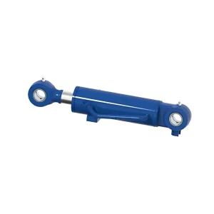
ODM Small Excavator Bulldozing Cylinder Manufacturers, Manufacturer
Product Details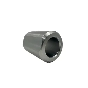
Wholesale Hydraulic Cylinder Bush MPM-HCBS11 Manufacturers, Manufacturer
Product Details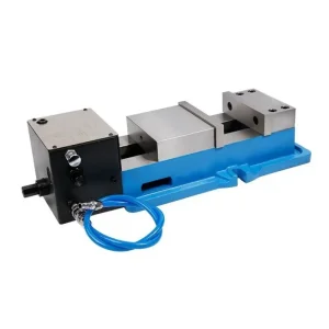
Custom Pneumatic Hydraulic Vise Suppliers, Manufacturer
Product Details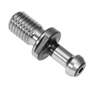
Best Retention Knob JIS B6339 Manufacturer, Factory
Product Details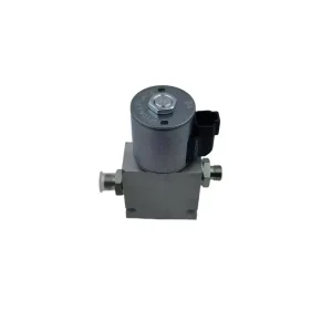
High-Quality Quick Change Solenoid Valve MPM-QCSV12 Suppliers, Factories
Product Details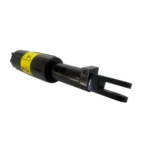
High-Quality Width Adjustment Cylinder for Reversible Plough Supplier, Factories
Product Details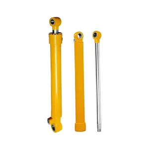
China Small Excavator Stick Cylinder Suppliers, Manufacturers
Product Details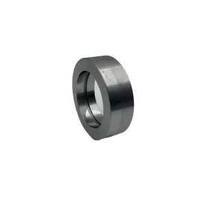
Custom Hydraulic Spherical Bearing MPM-HCSB11 Supplier, Factories
Product Details
Direct OEM Sourcing Partnership
Collaborate Directly with Qingdao Micro Precision Machinery
Send us your exact working pressure, relief cracking setpoint, flow rates, and mounting specifications. We furnish comprehensive CAD verification, material certificates, and rapid DDP/CIF export shipping logistics worldwide.