
Why Is a Boom Cylinder Important for Excavators?
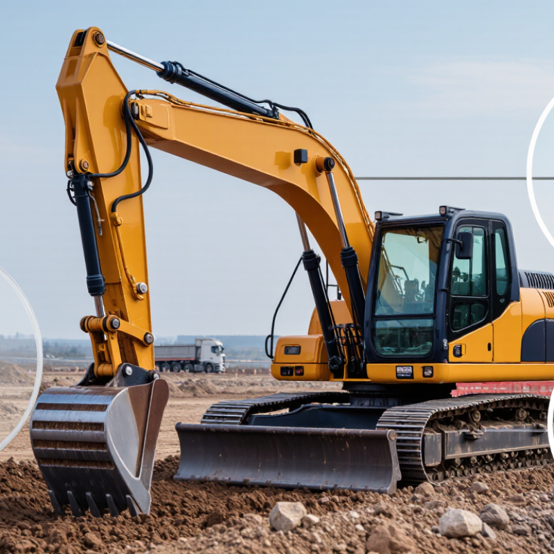
On an excavator, the boom does more than lift the arm above the tracks. It positions the bucket for digging, loading, and reaching across uneven ground. The Boom Cylinder supplies the hydraulic force that raises and lowers this heavy structure. Without steady cylinder movement, the operator may struggle to place the bucket accurately or keep work flowing smoothly. That matters.
The cylinder’s role becomes clear during everyday tasks. A loaded bucket swings toward a truck, then pauses while the operator adjusts its height. Hydraulic pressure moves the piston inside the cylinder, extending or retracting the rod to change the boom’s position. That movement must work with the machine’s other hydraulic components, not in isolation. Smooth control depends on sound components, suitable operating conditions, and careful machine use.
A boom cylinder also affects reliability and maintenance planning. Leaks, damaged hoses, unusual movement, or visible rod damage can signal a problem that needs inspection. Small signs count. Addressing them early may help reduce further wear, though symptoms alone cannot confirm the cause. The right response depends on the machine model and the condition found during assessment. Operators and technicians should follow the manufacturer’s service guidance rather than guess at pressure settings or repairs. In the sections ahead, we’ll look at how the Boom Cylinder works, why it matters to excavator performance, and what signs deserve attention. It is a vital component, but not a cure-all: good results still depend on the whole machine and the person operating it.
What a Boom Cylinder Is: A Double-Acting Hydraulic Actuator
A boom cylinder is a double-acting hydraulic actuator: it uses pressurized oil to move a piston in both directions. Oil enters one chamber to extend the piston rod, while oil entering the opposite chamber retracts it. The displaced oil leaves through the other port. This two-way action lets an excavator raise and lower its boom under controlled hydraulic power. It is not simply a powered hinge.
Inside the cylinder, the piston separates the two oil chambers, and seals help limit leakage across it. The rod transfers force through pinned connections to the boom structure. As the operator moves the control, a valve directs oil to the required side of the piston. Smooth motion depends on more than pressure; boom angle, load, and cylinder geometry also affect the force available. That detail is easy to overlook.
The mental picture is useful, but imperfect. A cylinder’s behavior changes with the load and the boom’s position, so the same control input may not feel identical throughout its travel. In practical inspections, technicians look for oil around seals, damage on the exposed rod, and looseness or unusual wear at the pins. Small signs matter. A leak or scored rod can reduce performance and may lead to further damage if ignored.
FAQS
It is a double-acting hydraulic actuator. Pressurized oil moves its piston in both directions, raising or lowering the boom.
Oil enters one chamber and pushes the piston rod outward. Oil entering the opposite chamber pulls it back. Displaced oil exits through another port.
A piston separates two oil chambers, while seals help limit leakage. The rod connects to the boom through pinned joints.
Hydraulic pressure matters, but so do piston area, boom angle, load, and cylinder geometry. One pressure figure cannot tell the whole story.
Stroke affects the cylinder’s travel and the boom’s working arc. Mounting points affect leverage, which can change as the boom moves.
No. The linkage angle and machine stability matter too. A longer stroke alone may not help much.
Check for oil around seals, scratches on the exposed rod, and looseness at the pins. Small signs matter.
The boom’s position and load change how the cylinder moves it. I sometimes picture it as a simple hinge, but that misses the geometry.
Conclusion
A Boom Cylinder is a double-acting hydraulic actuator that helps an excavator raise and lower its boom. Pressurized hydraulic oil acts on either side of the piston, allowing controlled movement in both directions. At typical operating pressures of 30–35 MPa, the cylinder can generate substantial lifting force. For example, a cylinder with a 100 mm bore produces about 236 kN of theoretical force at 30 MPa, although actual performance varies with system conditions and mechanical losses.
Cylinder stroke and mounting geometry also affect boom reach, movement, and lifting capacity. Longer strokes can support a wider range of motion, while the cylinder’s position influences how effectively its force is applied. Reliable operation depends on durable rods, properly functioning seals, and clean hydraulic oil. Together, these elements help maintain smooth boom movement, reduce wear, and support consistent performance over time.